drawable drawable常用作View的背景 (还可以作为ImageView中的图像来显示)。是通过xml来定义的。
Drawable是个抽象类,是所有Dreawble对象的基类,每个具体的Drawable是它的子类。这就反映了Drawable是可以通过代码来创建的。
分类 1.BitmapDrawable 表示一张图片,可以直接接引原始的图片,或者通过XML的方式描述。
2.ShapeDrawble 通过颜色构造的图形
3.LayerDrawable 将不同的Drawable放置在不同的层上面达到一种叠加效果。XML标签是,一个layer-list包含很多个item,一个item表示一个Drawable。item中的属性可以移动对应的Drawable。item中的andorid:drawable属性可以引用一个Drawable(故该drawable是已经存在的。)或者自己在item中定义一个。
4.StateListDrawable 对应着标签,表示的是drawable的集合,每个drawable对应view的一种状态,系统会根据view的状态来选择drawable
它包含许多个item(表示一个具体的Drawable)里面包含了view的状态。故系统自上而下根据view的状态选择item。(找到一个就返回,没找到就选择默认的item)默认的item是不附带状态的。
5.LevelListDrawable 对应标签,表示的是drawable集合,但是集合中的drawable是有等级的。根据不同的等级切换到不同的drawable。等级在item。view是通过设置等级来选择对应的drawable作为其背景的。(设置等级是通过Drawable类的setLevel方法来设置的)。
感觉上可以自由选择自己想要的背景。
6.TransitionDrawable 对应标签。实现两个 drawable之间的淡入淡出。
在其中确定自己的item(即item对应的drawable之前淡入淡出)
可以直接在view中设置为其背景
1
2
3
4
5
<ImageView android:id="@+id/imgView" android:layout_width="wrap_content" android:layout_height="wrap_content" android:src="@drawable/transition" />
或者在代码中控制
1
2
3
4
5
6
7
ImageView image = (ImageView) findViewById(R.id.mIv); TransitionDrawable transition = (TransitionDrawable)getResources(). getDrawable(R.drawable.transition_simple); image.setImageDrawable(transition); transition.startTransition(2000 );
问题:如何实现多个drawable的淡入淡出?
开启一个线程(死循环)每隔一段时间发送消息到UI主线程中替换主线程中的transitionDrawable对象中的图片就可以了,需要用到handler。
https://blog.csdn.net/z_zt_t/article/details/52761432
7.InsetDrawable 对应标签。可以将其他的drawable内嵌到自己的当中。故view可以让背景比自己的实际区域小。
很像drawable的padding属性,区别在于 padding表示drawable的内容与drawable本身的边距,insetDrawable表示两个drawable和容器之间的边距。
8.ScaleDrawable 对应与标签。根据自己的等级将其指定的drawable进行放缩。等级越小,放缩越好。等级为0,则不可见。
9.ClipDrawable 对应与标签。根据自己的等级设置一个Drawable的当前显示比例来裁剪出另一张Drawable。(该drawable是其引用的drawable的一部分)
https://blog.csdn.net/briblue/article/details/53528837
10.自定义Drawable 核心是draw方法(?)。系统调用draw方法来绘制view的背景。由此可得,可以通过重写drawable的draw方法来自定义drawable。
11.VectorDrawable Android矢量图I–VectorDrawable基础
Android API 21(5.0)引入了一个Drawable的子类VectorDrawable目的就是用来渲染矢量图,AnimatedVectorDrawable用来播放矢量动画。
准备
使用矢量图要根据minSdkVersion来分3中不同的情况:
minSdkVersion>=21:用xml文件或者代码定义VectorDrawable,和普通的Drawable用法一样,不再需要额外任何东西;如何编写矢量图,下文有介绍;minSdkVersion<21:如果想要渲染矢量图的话必须在app模块的build.gralde文件里添加一行代码:
1
2
3
defaultConfig { vectorDrawables.useSupportLibrary = true }
3. minSdkVersion<21以及更多:上面的第二种情况是使用兼容包,但是兼容包仅支持AppCompatImageView和AppCompatImageButton及其子类矢量图,而且矢量图的引用必须放在app:srcCompat属性中才会被识别并生效,代码必须这样写才行:
1 2 3 4 5 <android.support.v7.widget.AppCompatImageView app:layout_constraintBottom_toBottomOf ="parent" android:layout_width ="100dp" android:layout_height ="100dp" app:srcCompat ="@drawable/ic_oval" />
ic_oval.xml是我们使用xml编写的矢量图,如果想要TextView的drawableTop或者其他额外方式使用矢量图渲染,那么必须在Activity中加入代码:
1
2
3
static { AppCompatDelegate.setCompatVectorFromResourcesEnabled(true ); }
同时这个Activity必须继承AppCompatActivity这个compat兼容包属性才会生效。
minSdkVersion<21情况下在非app:srcCompat属性的地方使用矢量图时,需要将矢量图用drawable容器(如StateListDrawable, InsetDrawable, LayerDrawable, LevelListDrawable, 和RotateDrawable)包裹起来使用。否则会在低版本的情况下报错org.xmlpull.v1.XmlPullParserException: Binary XML file line #0: invalid drawable tag vector。minSdkVersion>=21则没有任何限制。
矢量图使用
准备工作做好之后,我们就需要自己动手编辑矢量图了。VectorDrawable类在xml中对应的是标签是vector。我目前所知道的是只有xml文件才能决定矢量图的样子(也就是编辑pathData、fillColor等属性),貌似无法使用代码来决定矢量图的绘制逻辑,而只能使用代码加载编辑好的xml文件,这个xml文件有两种方法来创建:
右击drawable–>Drawable resource file–>设置root element为vector,这样的矢量图绘制逻辑完全掌握在开发者手里;
右击drawable–>Vector Asset,选择SVG或者PSD文件直接生成根标签为vector的xml文件,可以百度或者Google怎样把png转换成SVG。
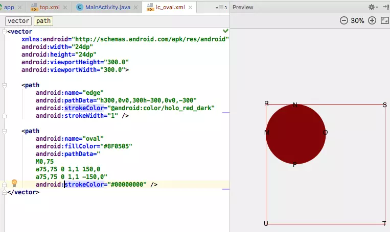
写了这么多字,一直在瞎扯淡而没谈重点,下面我们看下根标签为vector的xml文件的真面目,代码:
上图中标签vector使用了四个属性:android:width="24dp"、android:height="24dp"、android:viewportHeight="300.0"、android:viewportWidth="300.0"。
width和height:当使用这个矢量图的View的宽高是wrap_content 的时候这两个属性才生效;
viewportWidth和viewportHeight:决定画布的宽高,是定义的一个虚拟空间,方便编辑pathData属性,如果pathData中的点超出了这个虚拟空间,超出的部分将不会展现给用户;虚拟空间的原点仍然还是在左上角(R点就是原点)。
path标签是vector标签的子标签,它使用了以下属性:
android:name:类似View的id属性,方便path被引用,如上图的edge是虚拟空间四个边界的path,oval是一个椭圆的path;android:fillColor:填充path的颜色,如果没有定义则不填充pathandroid:strokeColor:path边框颜色,如果没有定义则不显示边框android:strokeWidth:path边框的粗细尺寸android:pathData:path指令,决定path的移动和绘制逻辑,这个是最主要的属性,下面详细讨论。
更多path属性请参考链接 。
pathData的指令和Path类的API方法基本差不多,比如M指令对应moveTo方法,m指令对应rMoveTo方法,下面是一些基本的指令:
Mx,y:移动到点(x,y)
Lx,y:直线连到点x,y,简化命令H(x)水平连接和V(y)垂直连接;
Qx1,y1 x2,y2:二阶贝塞尔曲线,控制点(x1,y1),终点x2,y2;
Cx1,y1 x2,y2 x3,y3:三阶贝塞尔曲线,控制点(x1,y1)( x2,y2),终点x3,y3;
Tx y:平滑的二阶贝塞尔曲线,参数只有一个点(x,y),这个点是结束点,控制点是前一个二阶贝塞尔曲线的控制点相对于前一个贝塞尔曲线的结束点的镜像点。
Sx2,y2 x,y:平滑的三阶贝塞尔曲线,参数为(x2,y2 x,y) ,x2,y2 为第二个控制点,x,y为绘制终点,那么第一个控制点则是前一个三阶曲线的第二个控制点相对于前一个三阶曲线终点的镜像点。
Arx,ry x-axis-rotation large-arc-flag,sweep-flag x,y:ellipse arc圆弧曲线
z:close闭合
每个指令都有大小写形式,大写表示后面的参数是绝对坐标,小写表示相对于上一个点的相对坐标位置,参数可以用逗号或者空格分离。链接 。
估计你已经发现了,圆弧曲线指令A竟然那么多参数,这直接吓跑了很多的程序员,其实也并不难,且慢慢道来。
先根据图1里的代码来分析pathData指令。如图一所示,edge这个path使用了四个相对指令,首先指令h300 0相对向右水平移动300到点S,然后指令v0 300相对向下垂直移动300到T,再次指令h-300 0相对向左水平移动300到U,最后指令v0 -300相对向上垂直移动300到起点R,这样就根据属性strokeColor和strokeWidth绘制了四条直线,最后一个指令可以使用z代替。这很简单吧?!
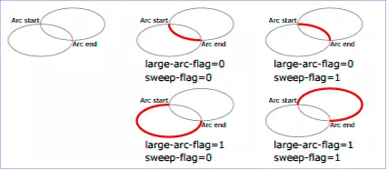
再来看oval这个path。它使用了三条指令。第一条指令移动到点M处,第二条指令a75,75 0 1,1 150,0绘制M-N-O的弧线,第三条指令a75,75 0 1,1 -150,0绘制O-P-M的弧线。a指令共有7个参数:rx和ry表示椭圆的两个半径,x-axis-rotation表示x轴的旋转角度,x和y表示绘制椭圆弧线的终点,这5个参数很简单很好理解,large-arc-flag和sweep-flag这两个参数有点唬人。
图2
看图2希望你能明白这两个参数的意义。
有人可能会问,图1的oval path是个圆,竟然使用了两个a指令,使用一个a指令就能绘制圆的,只要终点回到起始点就能绘制圆的path了,刚开始我也是这样认为的,比如下面的代码:
1 2 3 4 5 6 7 8 9 10 11 12 13 14 <vector xmlns:android ="http://schemas.android.com/apk/res/android" android:width ="24dp" android:height ="24dp" android:viewportHeight ="300.0" android:viewportWidth ="300.0" > <path android:name ="circle" android:fillColor ="@android:color/holo_green_light" android:pathData =" M150,150 a75,75 0 1,1 0,0" android:strokeColor ="#00000000" /> </vector >
上面的代码的path从起始点又回到了起始点,不会绘制任何东西,终点x y需要和起始点错开几个像素比如android:pathData="M150,150 a75,75 0 1,1 0,1"就大约是一个圆path,为什么说是大约一个圆?因为起始点和终点不在一起,这只是一个圆的大弧线部分。推荐使用两条a指令绘制圆path,因为一条a指令绘制的不是真正的圆path。
group标签
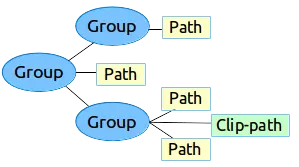
path没有scale 、rotate 和translate 这三种属性,因此也不能执行这三种属性动画,要达到这样的目的需要借助group这个标签。group标签也是vector的一个子标签,它可以作为path或者其他group的父标签使用,将path和group组合成一个组来附加一些变换操作,这些变换操作包括scale 、rotate 和translate 共三种。这张图3是来自android官网 的vector标签树型图:
图3
。定义变换的细节,定义裁剪区域。根据这三个变换操作,group标签有以下属性:
android:name:group的名字;
android:rotation:group的旋转角度,默认0。
android:pivotX:scale和rotation变换中心点的X坐标,默认0;
android:pivotY:scale和rotation变换中心点的Y坐标,默认0;
android:scaleX:X轴方向的缩放,默认1;
android:scaleY:Y轴方向的缩放,默认1;
android:translateX:X轴方向的移动距离,默认0;
android:translateY:Y轴方向的移动距离,默认0。
这是group的全部属性了,属性都很简单,不需要解释。
clip-path标签
定义当前绘制的剪切路径,就是图像的一部分剪切下来。注意,clip-path只对当前的vector和group以及当前vector和group的孩子有效。这个标签仅有两个属性:
android:name:clip-path的名字;
android:pathData:clip-path的路径。
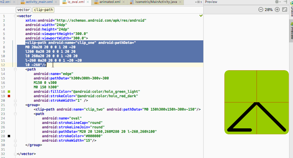
1 2 3 4 5 6 7 8 9 10 11 12 13 14 15 16 17 18 19 20 21 22 23 24 25 26 27 28 29 30 31 <vector xmlns:android ="http://schemas.android.com/apk/res/android" android:width ="24dp" android:height ="24dp" android:viewportHeight ="300.0" android:viewportWidth ="300.0" > <clip-path android:name ="clip_one" android:pathData =" M0 20a20 20 0 0 1 20 -20 l260 0a20 20 0 0 1 20 20 l0 260a20 20 0 0 1 -20 20 l-260 0a20 20 0 0 1 -20 -20 l0 -260" /> <path android:name ="edge" android:pathData ="h300v300h-300v-300 M150 0 v300 M0 150 h300" android:fillColor ="@android:color/holo_green_light" android:strokeColor ="@android:color/holo_red_dark" android:strokeWidth ="1" /> <group > <clip-path android:name ="clip_two" android:pathData ="M0 150h300v150h-300v-150" /> <path android:name ="oval" android:strokeLineCap ="round" android:strokeLineJoin ="round" android:pathData ="M20 20 l260,260M280 20 l-260,260h100" android:strokeColor ="#000000" android:strokeWidth ="15" /> </group > </vector >
上面代码定义了两个clip-path,其效果如图4所示。
图4.gif
build.gradle中vectorDrawables.useSupportLibrary属性
build.gradle中的vectorDrawables.useSupportLibrary默认是false,不设置为true的话会有什么问题吗?讨论这个问题也需要根据minSdkVersion具体分析:
minSdkVersion>=21:这么高的API根本就不需要兼容包,仍然可以渲染矢量图;minSdkVersion<21:不再使用矢量图兼容包,不能渲染矢量图,但是有趣的是vector标签仍然可以使用,低版本的API完全把VectorDrawable当作Drawable使用了,VectorDrawable的特性完全失效。原理是vector xml文件会生成对应的png文件,使用png方式渲染图片,和矢量图没有任何关系。值得注意的是生成的png图片size很小而且会忽略vector标签的android:tint属性(貌似只忽略这个属性,我试过vector标签的android:alpha属性在生成的png图片中仍然有效,生成的png文件目录是app/build/generated/res/pngs/debug,minSdkVersion>=21或者vectorDrawables.useSupportLibrary=true的话不会生成这些png图片)。而且path标签的color相关的属性不能引用colors.xml的值,android:strokeColor="@android:color/holo_red_dark"这样写的话会编译失败,提示错误:Can't process attribute android:strokeColor="@android:color/holo_red_dark": references to other resources are not supported by build-time PNG generation,而只能写原生的16进制color值比如android:strokeColor="#234aac"。
想看具体信息请查看这篇文章 。
SVG实战
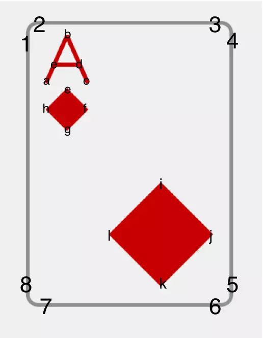
我做的项目中一张扑克png资源大小2k左右,我试着用矢量图画这些扑克牌。代码如下:
1 2 3 4 5 6 7 8 9 10 11 12 13 14 15 16 17 18 19 20 21 22 23 24 25 26 27 28 <vector xmlns:android ="http://schemas.android.com/apk/res/android" xmlns:tools ="http://schemas.android.com/tools" android:width ="400dp" android:height ="550dp" android:viewportHeight ="550" android:viewportWidth ="400.0" > <group android:name ="poker_diamond_a" > <path android:name ="border" android:strokeWidth ="7" android:strokeColor ="#96999c" android:fillColor ="@android:color/white" android:pathData ="M5 25a20 20 0 0 1 20 -20 h350a20 20 0 0 1 20 20v500a20 20 0 0 1 -20 20h-350a20 20 0 0 1 -20 -20v-500" /> <path android:name ="a" android:strokeWidth ="8" android:strokeColor ="#cc0000" android:strokeLineJoin ="bevel" android:pathData ="M40 120 l40 -90 l40 90 l-16-35 h-48" /> <path android:name ="small_diamond" android:fillColor ="#cc0000" android:pathData ="M80 130l41 41l-41 41l-41 -41z" /> <path android:name ="big_diamond" android:fillColor ="#cc0000" android:pathData ="M260 310l100 100l-100 100l-100 -100z" /> </group > </vector >
图5
代码很简单,只有4条path。border路径顺序是1-2-3-4-5-6-7-8-1, a的路径是a-b-c-d-e,small_diamond的路径是e-f-g-h,big_diamond的路径是i-j-k-l。这个xml文件只有1k。
vector属性
android:alpha:矢量图的透明度,范围0-1,默认1;android:tint:矢量图的颜色,这个颜色值会覆盖所有与color相关的属性比如path的fillColor和strokeColor等;这个属性会被API setColorFilter(ColorFilter)覆盖。android:tintMode:色彩混合模式,可选值有很多,下面详细讨论,默认src_in。android:autoMirrored:当布局方向变成right-to-left的时候,矢量图是否自动镜像,默认false,这个属性在API>=19才生效。
关于tintMode,先看下PorterDuff这类的源码:
1
2
3
4
5
6
7
8
9
10
11
12
13
14
15
16
17
18
19
20
21
22
23
24
25
26
27
28
29
30
31
public class PorterDuff { public PorterDuff () { throw new RuntimeException ("Stub!" ); } public static enum Mode { CLEAR, DST, DST_ATOP, DST_IN, DST_OUT, DST_OVER, SRC, SRC_ATOP, SRC_IN, SRC_OUT, SRC_OVER, DARKEN, XOR, LIGHTEN, MULTIPLY, SCREEN, ADD, OVERLAY; private Mode () { } } }
首先类名PorterDuff是什么意思呢?PorterDuff是两个人名的组合: Thomas Porter和Tom Duff,他们1984年在ACM SIGGRAPH计算机图形学发表论文《Compositing digital images》,最早提出图形混合概念,极大地推动了图形图像学的发展,有兴趣的同学可以自行查阅资料。
图1
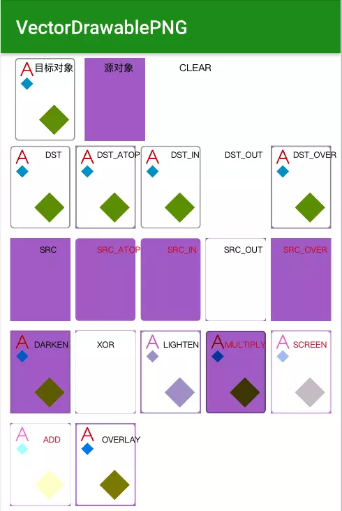
PorterDuff共有18个模式可选,但是android:tintMode可选值只有六个:MULTIPLY、SCREEN、ADD、SRC_ATOP、SRC_IN、SRC_OVER,(xml文件只提供这6个的原因我不知道,请大神留言告知)。当然想使用其余12个tintMode模式也是可以的,需要用代码调用API Drawable.setTintMode(PorterDuff.Mode)即可,可以达到相应tintMode的效果。
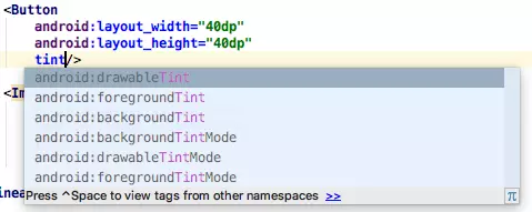
tint属性是Android 5.0引入的,Android 6.0又引入了drawableTint的属性。
图2
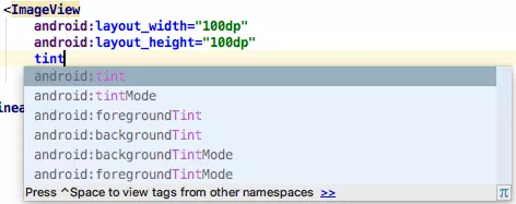
ImageView会多出下面6个属性:
图3
图4
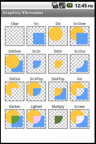
我们对矢量图进行调色,先看效果如图4所示,图4中红色文字表示xml允许使用的6个tintMode。下面贴出代码:
1
2
3
4
5
6
7
8
9
10
11
12
13
14
15
16
17
18
19
20
21
22
23
24
25
26
27
28
29
30
31
32
33
34
35
36
37
38
39
40
41
42
43
44
45
46
47
48
49
50
51
52
53
54
55
56
57
58
59
60
61
62
63
64
65
66
67
68
69
70
71
72
73
74
75
76
77
78
79
80
81
82
83
84
85
86
87
88
89
90
91
92
93
94
95
96
97
98
99
100
101
102
103
104
105
106
107
108
109
110
111
112
113
114
115
116
117
118
119
120
121
122
123
124
125
126
127
128
129
130
131
132
133
134
135
136
137
138
139
140
141
142
143
144
145
146
147
148
149
150
151
152
153
154
155
156
157
158
159
160
161
162
163
164
165
166
167
168
169
170
171
172
173
174
175
176
177
178
179
180
181
182
183
184
185
186
187
188
// poker_a.xml <vector xmlns:android ="http://schemas.android.com/apk/res/android" android:width ="400dp" android:height ="550dp" android:tint ="@android:color/holo_purple" android:viewportHeight ="550" android:viewportWidth ="400.0" > <group android:name ="poker_diamond_a" > <path android:name ="border" android:strokeWidth ="7" android:strokeColor ="#96999c" android:fillColor ="@android:color/white" android:pathData ="M5 25a20 20 0 0 1 20 -20 h350a20 20 0 0 1 20 20v500a20 20 0 0 1 -20 20h-350a20 20 0 0 1 -20 -20v-500" /> <path android:name ="a" android:strokeWidth ="8" android:strokeColor ="@android:color/holo_red_dark" android:strokeLineJoin ="bevel" android:pathData ="M40 120 l40 -90 l40 90 l-16-35 h-48" /> <path android:name ="small_diamond" android:fillColor ="@android:color/holo_blue_dark" android:pathData ="M80 130l41 41l-41 41l-41 -41z" /> <path android:name ="big_diamond" android:fillColor ="@android:color/holo_green_dark" android:pathData ="M260 310l100 100l-100 100l-100 -100z" /> </group > </vector > <dimen name ="width" > 64dp</dimen > <dimen name ="height" > 88dp</dimen > // activity_main.xml <?xml version="1.0" encoding="utf-8" ?> <LinearLayout xmlns:android ="http://schemas.android.com/apk/res/android" xmlns:app ="http://schemas.android.com/apk/res-auto" xmlns:tools ="http://schemas.android.com/tools" android:layout_width ="match_parent" android:layout_height ="match_parent" android:orientation ="vertical" android:padding ="5dp" > <LinearLayout android:layout_width ="match_parent" android:layout_height ="wrap_content" android:orientation ="horizontal" > <ImageView android:layout_width ="@dimen/width" android:layout_height ="@dimen/height" android:src ="@drawable/poker_a" android:layout_marginLeft ="10dp" android:tint ="@android:color/transparent" /> <View android:layout_width ="@dimen/width" android:layout_height ="@dimen/height" android:layout_marginLeft ="10dp" android:background ="@android:color/holo_purple" /> <ImageView android:id ="@+id/CLEAR" android:layout_width ="@dimen/width" android:layout_height ="@dimen/height" android:src ="@drawable/poker_a" android:layout_marginLeft ="10dp" /> </LinearLayout > <LinearLayout android:layout_width ="match_parent" android:layout_height ="wrap_content" android:orientation ="horizontal" android:padding ="5dp" > <ImageView android:id ="@+id/DST" android:layout_width ="@dimen/width" android:layout_height ="@dimen/height" android:src ="@drawable/poker_a" /> <ImageView android:id ="@+id/DST_ATOP" android:layout_width ="@dimen/width" android:layout_height ="@dimen/height" android:src ="@drawable/poker_a" android:layout_marginLeft ="5dp" /> <ImageView android:id ="@+id/DST_IN" android:layout_width ="@dimen/width" android:layout_height ="@dimen/height" android:src ="@drawable/poker_a" android:layout_marginLeft ="5dp" /> <ImageView android:id ="@+id/DST_OUT" android:layout_width ="@dimen/width" android:layout_height ="@dimen/height" android:src ="@drawable/poker_a" android:layout_marginLeft ="5dp" /> <ImageView android:id ="@+id/DST_OVER" android:layout_width ="@dimen/width" android:layout_height ="@dimen/height" android:src ="@drawable/poker_a" android:layout_marginLeft ="5dp" /> </LinearLayout > <LinearLayout android:layout_width ="match_parent" android:layout_height ="wrap_content" android:orientation ="horizontal" android:padding ="5dp" > <ImageView android:id ="@+id/SRC" android:layout_width ="@dimen/width" android:layout_height ="@dimen/height" android:src ="@drawable/poker_a" /> <ImageView android:id ="@+id/SRC_ATOP" android:layout_width ="@dimen/width" android:layout_height ="@dimen/height" android:src ="@drawable/poker_a" android:layout_marginLeft ="5dp" /> <ImageView android:id ="@+id/SRC_IN" android:layout_width ="@dimen/width" android:layout_height ="@dimen/height" android:src ="@drawable/poker_a" android:layout_marginLeft ="5dp" /> <ImageView android:id ="@+id/SRC_OUT" android:layout_width ="@dimen/width" android:layout_height ="@dimen/height" android:src ="@drawable/poker_a" android:layout_marginLeft ="5dp" /> <ImageView android:id ="@+id/SRC_OVER" android:layout_width ="@dimen/width" android:layout_height ="@dimen/height" android:src ="@drawable/poker_a" android:layout_marginLeft ="5dp" /> </LinearLayout > <LinearLayout android:layout_width ="match_parent" android:layout_height ="wrap_content" android:orientation ="horizontal" android:padding ="5dp" > <ImageView android:id ="@+id/DARKEN" android:layout_width ="@dimen/width" android:layout_height ="@dimen/height" android:src ="@drawable/poker_a" /> <ImageView android:id ="@+id/XOR" android:layout_width ="@dimen/width" android:layout_height ="@dimen/height" android:src ="@drawable/poker_a" android:layout_marginLeft ="5dp" /> <ImageView android:id ="@+id/LIGHTEN" android:layout_width ="@dimen/width" android:layout_height ="@dimen/height" android:src ="@drawable/poker_a" android:layout_marginLeft ="5dp" /> <ImageView android:id ="@+id/MULTIPLY" android:layout_width ="@dimen/width" android:layout_height ="@dimen/height" android:src ="@drawable/poker_a" android:layout_marginLeft ="5dp" /> <ImageView android:id ="@+id/SCREEN" android:layout_width ="@dimen/width" android:layout_height ="@dimen/height" android:src ="@drawable/poker_a" android:layout_marginLeft ="5dp" /> </LinearLayout > <LinearLayout android:layout_width ="match_parent" android:layout_height ="wrap_content" android:orientation ="horizontal" android:padding ="5dp" > <ImageView android:id ="@+id/ADD" android:layout_width ="@dimen/width" android:layout_height ="@dimen/height" android:src ="@drawable/poker_a" /> <ImageView android:id ="@+id/OVERLAY" android:layout_width ="@dimen/width" android:layout_height ="@dimen/height" android:src ="@drawable/poker_a" android:layout_marginLeft ="5dp" /> </LinearLayout > </LinearLayout >
MainActivity.java代码:
1 2 3 4 5 6 7 8 9 10 11 12 13 14 15 16 17 18 19 20 21 22 23 24 25 26 27 28 29 30 31 32 33 public class MainActivity extends AppCompatActivity { static { AppCompatDelegate.setCompatVectorFromResourcesEnabled(true ); } @Override protected void onCreate (Bundle savedInstanceState) { super .onCreate(savedInstanceState); setContentView(R.layout.activity_main); ((ImageView) findViewById(R.id.CLEAR)).getDrawable().mutate().setTintMode(PorterDuff.Mode.CLEAR); ((ImageView) findViewById(R.id.DST)).getDrawable().mutate().setTintMode(PorterDuff.Mode.DST); ((ImageView) findViewById(R.id.DST_ATOP)).getDrawable().mutate().setTintMode(PorterDuff.Mode.DST_ATOP); ((ImageView) findViewById(R.id.DST_IN)).getDrawable().mutate().setTintMode(PorterDuff.Mode.DST_IN); ((ImageView) findViewById(R.id.DST_OUT)).getDrawable().mutate().setTintMode(PorterDuff.Mode.DST_OUT); ((ImageView) findViewById(R.id.DST_OVER)).getDrawable().mutate().setTintMode(PorterDuff.Mode.DST_OVER); ((ImageView) findViewById(R.id.SRC)).getDrawable().mutate().setTintMode(PorterDuff.Mode.SRC); ((ImageView) findViewById(R.id.SRC_ATOP)).getDrawable().mutate().setTintMode(PorterDuff.Mode.SRC_ATOP); ((ImageView) findViewById(R.id.SRC_IN)).getDrawable().mutate().setTintMode(PorterDuff.Mode.SRC_IN); ((ImageView) findViewById(R.id.SRC_OUT)).getDrawable().mutate().setTintMode(PorterDuff.Mode.SRC_OUT); ((ImageView) findViewById(R.id.SRC_OVER)).getDrawable().mutate().setTintMode(PorterDuff.Mode.SRC_OVER); ((ImageView) findViewById(R.id.DARKEN)).getDrawable().mutate().setTintMode(PorterDuff.Mode.DARKEN); ((ImageView) findViewById(R.id.XOR)).getDrawable().mutate().setTintMode(PorterDuff.Mode.XOR); ((ImageView) findViewById(R.id.LIGHTEN)).getDrawable().mutate().setTintMode(PorterDuff.Mode.LIGHTEN); ((ImageView) findViewById(R.id.MULTIPLY)).getDrawable().mutate().setTintMode(PorterDuff.Mode.MULTIPLY); ((ImageView) findViewById(R.id.SCREEN)).getDrawable().mutate().setTintMode(PorterDuff.Mode.SCREEN); ((ImageView) findViewById(R.id.ADD)).getDrawable().mutate().setTintMode(PorterDuff.Mode.ADD); ((ImageView) findViewById(R.id.OVERLAY)).getDrawable().mutate().setTintMode(PorterDuff.Mode.OVERLAY); } }
色彩混合涉及到两个对象,目标对象 和源对象 ,这里的目标对象是poker_a.xml这个矢量图,源对象是tint设置的颜色值,为啥这样说呢,记着这个原则,先绘制的是目标对象,我们就是要对目标对象进行调色。对目标对象调色后的对象叫做复合对象 。
有了这两个对象,怎么进行调色呢?这里有很多计算公式,公式中又有很多元素,先来看下这些元素:
1
2
3
4
5
* Sa:Source alpha,源对象的Alpha通道; * Sc:Source color ,源对象的颜色; * Da:Destination alpha,目标对象的Alpha通道; * Dc:Destination color ,目标对象的颜色; * [a,c] :对象的ARGB值,a 表示alpha,c表示color 。
下面对这18个tintMode进行剖析,该文受到这篇文章 的启发。CLEAR
DST DST_ATOP DST_IN DST_OUT DST_OVER
SRC SRC_ATOP SRC_IN SRC_OUT SRC_OVER
DARKEN Da, Sc (1 - Da) + Dc*(1 - Sa) + min(Sc, Dc)],顾名思义,效果会变暗。进行对应像素比较,取较暗值(即较小值),如果色值相同则进行混合;如果两个对象都完全不透明,取较暗值,否则使用上面算法进行计算,受到源对象和目标对象对应色值和alpha值影响。结果复合对象的alpha值会变大。XOR [Sa + Da - 2 * Sa * Da, Sc * (1 - Da) + (1 - Sa) * Dc],不相交的地方按原样绘制源对象和目标对象,相交的地方受到对应alpha和颜色值影响,按公式进行计算,如果都完全不透明则相交处完全不绘制。LIGHTEN [Sa + Da - SaDa, Sc (1 - Da) + Dc*(1 - Sa) + max(Sc, Dc)],顾名思义,效果会变亮。进行对应像素比较,取较亮值(即较大值),如果色值相同则进行混合;如果两个对象都完全不透明,取较亮值,否则使用上面算法进行计算,受到源对象和目标对象对应色值和alpha值影响。MULTIPLY SCREEN
ADD OVERLAY
这18个模式终于介绍完了,再次感谢这篇文章 的作者。
path属性
android:strokeLineCap:顾名思义,设置线条的帽子,round圆角、square正方形、butt臀,默认是butt;
android:strokeLineJoin:线条拐弯处的样式,round圆角、bevel斜角、miter斜切尖角,默认是miter;
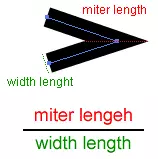
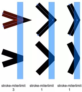
android:strokeMiterLimit:android:strokeLineJoin为miter的时候这个属性才发挥作用。设置miter斜切尖角长度(用miter_length表示)与线条宽度(用line_width表示)比例值的上限,默认是4,strokeMiterLimit = miter_length / line_width,这个属性设定了这个比例的最大值,超过这个值的尖角不再显示尖角而是bevel斜角。
图5
图6
如果你希望尖角多一些,就把这个属性设置大一些。在特别尖的拐弯处的点,点的这个比例可能大与strokeMiterLimit,那么就不显示尖角效果而是类似bevel斜角的效果,这样看起来不是很突兀,比较美观。
图5和图6来自
文章
;
android:trimPathStart:从路径起始位置截断路径的比率,取值范围0-1,默认0;
android:trimPathEnd:从路径结束位置截断路径的比率,取值范围0-1,默认1;
android:trimPathOffset:设置路径截取的偏移比例,取值范围0-1,默认0;链接
android:fillType:API 24才引入的这个属性,取值nonZero和evenOdd,默认nonZero。
关于android:fillType这个属性,需要花点篇幅讨论下。讨论这个属性之前,先看下代码及其对应的效果:
1
2
3
4
5
6
7
8
9
10
11
12
13
14
15
16
17
18
19
20
21
22
23
<?xml version="1.0" encoding="utf-8" ?> <?xml version="1.0" encoding="utf-8" ?> <vector xmlns:android ="http://schemas.android.com/apk/res/android" android:width ="200dp" android:height ="200dp" android:viewportHeight ="600" android:viewportWidth ="600" > <path android:name ="noneZero" android:strokeWidth ="2" android:strokeColor ="#B32D20" android:fillColor ="#3C8FC1" android:pathData ="M20 120 a100 100 0 1 1 200 0 a100 100 0 1 1 -200 0 M40 120 a80 80 0 1 1 160 0 a80 80 0 1 1 -160 0" /> <path android:name ="evenOdd" android:strokeWidth ="2" android:strokeColor ="#B32D20" android:fillColor ="#3C8FC1" android:fillType ="evenOdd" android:pathData ="M260 120 a100 100 0 1 1 200 0 a100 100 0 1 1 -200 0 M280 120 a80 80 0 1 1 160 0 a80 80 0 1 1 -160 0" /></vector >
图7
代码中有两条path,前者的fillType是默认的noneZero,后者的fillType是evenOdd,除了这两个属性外,其余属性一模一样(name属性和M指令的起始位置为了显示的区别,忽略好吧😄)。两者的效果图如图7所示。fillType的原理是什么呢?为啥会导致这样的效果呢?
这里需要提一点,代码中每一条path都绘制了两个圆,四个圆的每一个圆都是通过两条a指令绘制完成的,如果你不清楚a指令的参数,请仔细看完Android矢量图I–VectorDrawable基础 这篇文章并搞明白a指令后再回来看本文。这8条a指令的第5个参数都是1表示顺时针,请记住都是顺时针,因为fillType属性值noneZero跟path的方向有很大关系。
首先来看下默认的noneZero值。多看维基百科 ,那里的解释最权威。有一个多边形C,我们判断是否要对C的子多边形C1形成的一块区域进行填充,那么先定义一个变量value=0,根据value的值来决定是否对C1进行填充;在这个C1区域内任意选择一个点P,从这个点P向任意方向发射一条无限长的直线L,但是这个方向需要直线L与C1至少有一个交点,然后找出直线L与C所有的交点,每个交点处的方向是顺时针value++,顺时针value–,如果最后的value不是0,那么就对C1填充,否则不填充。
图8
为了加深下印象,再来举个例子。看下面的代码:
1
2
3
4
5
6
7
8
9
10
11
12
13
<?xml version="1.0" encoding="utf-8" ?> <vector xmlns:android ="http://schemas.android.com/apk/res/android" android:width ="200dp" android:height ="200dp" android:viewportHeight ="600" android:viewportWidth ="600" > <path android:strokeWidth ="2" android:strokeColor ="#B32D20" android:fillColor ="#3C8FC1" android:pathData ="M20 320 a100 100 0 1 0 200 0 M40 320 a80 80 0 1 1 160 0 a80 80 0 1 1 -160 0" /></vector >
图9
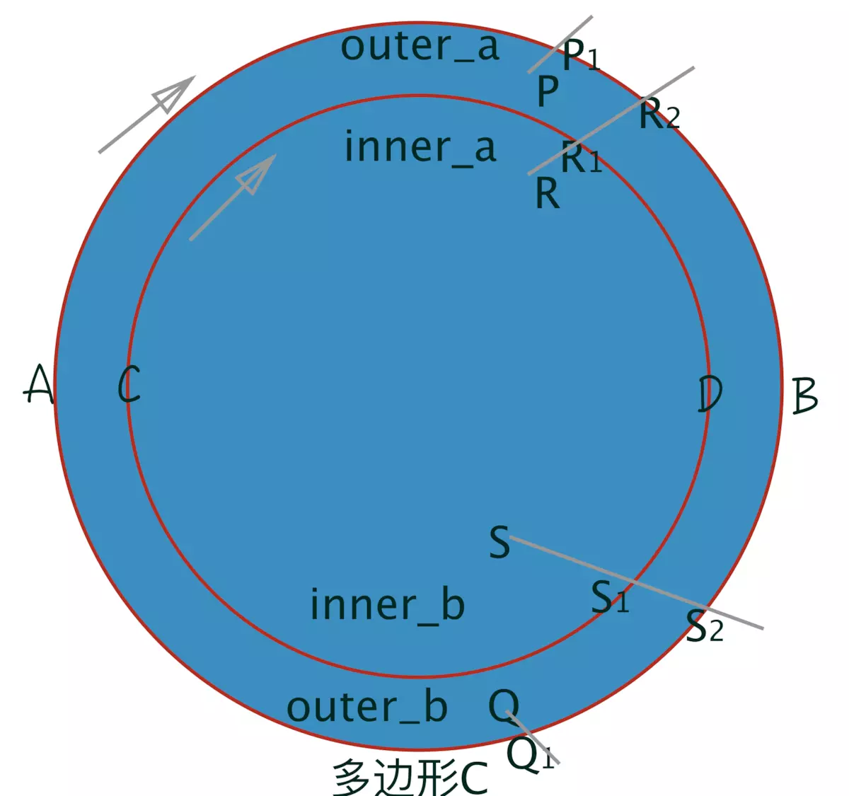
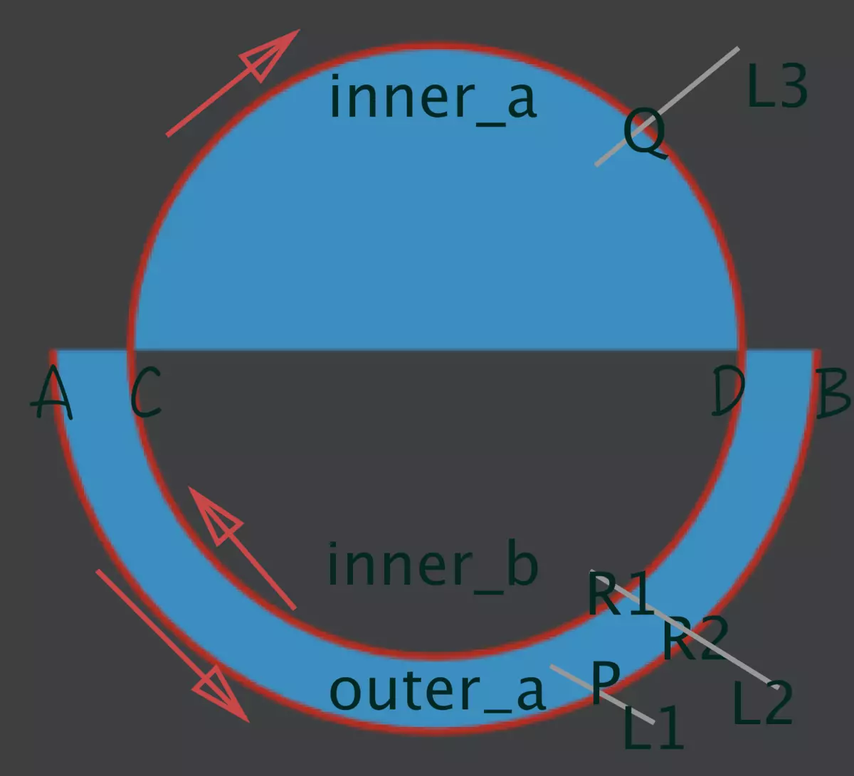
你运行上面的代码,不出问题的矢量图应该如图9所示。代码首先从A到B逆时针绘制椭圆弧,然后从C到D顺时针绘制椭圆弧,最后从D到C顺时针绘制椭圆弧。最终的多边形C包含三个子区域outer_a、inner_a、inner_b。对于outer_a,其value=P=-1,非0那就填充;对于inner_a,其value=Q1=1,非0那就填充;对于inner_b,其value=R1+R2=1+(-1)=0,0那就不填充。
如果你已经明白了noneZero,那么evenOdd就非常非常简单了,先看维基百科 ,它与指针方向没有关系了,一句话你就能明白:如果虚拟直线与多边形C的交点数目为奇数就填充内部,偶数就不填充内部 。如果还不明白,就举个例子,看代码:
1
2
3
4
5
6
7
8
9
10
11
12
13
14
<?xml version="1.0" encoding="utf-8" ?> <vector xmlns:android ="http://schemas.android.com/apk/res/android" android:width ="200dp" android:height ="200dp" android:viewportHeight ="600" android:viewportWidth ="600" > <path android:strokeWidth ="2" android:strokeColor ="#B32D20" android:fillColor ="#3C8FC1" android:fillType ="evenOdd" android:pathData ="M20 320 a100 100 0 1 0 200 0 M40 320 a80 80 0 1 1 160 0 a80 80 0 1 1 -160 0" /></vector >
上面代码的结果也是如图9所示,那么拿图9来解释:对于outer_a,其只有一个交点P,奇数那就填充;对于inner_a,其只有一个交点Q,奇数那就填充;对于inner_b,有两个交点R1和R2,偶数那就不填充。
怀着紧张的心情,fillType属性终于介绍了完了,真害怕写错而误导读者,如果有错误的地方或者有更好的分析方法,请大神批评指正。这里有两篇文章,帮助理解fillType:文章1 、文章2 。再说一点,如果你是用tint属性对矢量图进行调色,注意fillType属性值会对结果造成同样的影响 。
1 2 3 4 5 6 7 8 9 10 11 12 13 14 15 16 17 18 19 20 21 22 23 24 25 26 27 28 29 30 public enum FillType { WINDING (0 ), EVEN_ODD (1 ), INVERSE_WINDING (2 ), INVERSE_EVEN_ODD (3 ); FillType (int ni) { nativeInt = ni; } final int nativeInt; }
对这另外两种fillType,Google程序员的注释已经解释的很清楚了,我就不解释了,否则可能越解释越乱,越乱越糊涂。
mipmap
我们创建新项目时,它会帮助我们自动生成六个文件夹(密度不同):
drawable-ldpi (low:120dip)
drawable
drawable-mdpi (medium:160dip)
drawable-hdpi (high :240dip)
drawable-xhdpi (xhigh :320dip)
drawable-xxhdpi (xxhigh:480dip)
一般的做法是,将图片等资源放在drawable-hdip中,将一些和XML文件相关的内容(图片选择器、文字颜色选择器、自定义形状等)放在drawable中。
Google推荐:像素使用dip,文字使用sp 。并且没有推荐图片放在mipmap中。
在mdip文件夹,1dip=1px。
关于dp,dip,sp,pt,px的区别,可参考:附录一 。
关于图片在不同目录下的显示举例,可参考:附录二 。
官方解释:
附录一
dip : device independent pixels(设备独立像素). 不同设备有不同的显示效果,这个和设备硬件有关,一般我们为了支持WVGA、HVGA和QVGA 推荐使用这个,不依赖像素。
dp : 和dip相同。
px : pixels(像素),一个像素通常被视为图像的最小的完整采样,不同设备显示效果相同,一般我们HVGA代表320x480像素,这个用的比较多。
pt : point,是一个标准的长度单位,1pt=1/72英寸,用于印刷业,非常简单易用。
sp : scaled pixels(放大像素). 主要用于字体显示best for textsize。
in :(英寸):长度单位。
分辨率 :分为显示分辨率(屏幕分辨率) 和图像分辨率 。
显示分辨率:屏幕图像的精密度,是指显示器所能显示的像素有多少。显示器可 显示的像素越多,画面就越精细。显示分辨率一定的情况下,显示屏越小图像越清晰,反之,显示屏大小固定时,显示分辨率越高图像越清晰。
图象分辨率 :单位英寸中所包含的像素点数。
换算公式
1
2
3
4
5
6
7
8
9
10
11
12
13
14
15
16
17
18
public static float applyDimension (int unit, float value, DisplayMetrics metrics) { switch (unit) { case COMPLEX_UNIT_PX: return value; case COMPLEX_UNIT_DIP: return value * metrics.density; case COMPLEX_UNIT_SP: return value * metrics.scaledDensity; case COMPLEX_UNIT_PT: return value * metrics.xdpi * (1.0f /72 ); case COMPLEX_UNIT_IN: return value * metrics.xdpi; case COMPLEX_UNIT_MM: return value * metrics.xdpi * (1.0f /25.4f ); } return 0 ; }
附录二
mdpi与hdpi是2:3的关系
dp与px换算公式:
pixs =dips * (densityDpi/160).
dips=(pixs*160)/densityDpi
现在假设,在一个项目中,你将一张60px60px的图片放到mdpi中,它的大小是60 60;
若把它拿到hdpi中,那么它的大小应该是40*40,图片缩小。
结论: mipmap仅仅用于应用启动图标,可以根据不同分辨率进行优化。其他的图标资源,还是要放到drawable文件夹中。